Aero Dynamics reveals exciting progress in KC-10/DC-10 development for MSFS
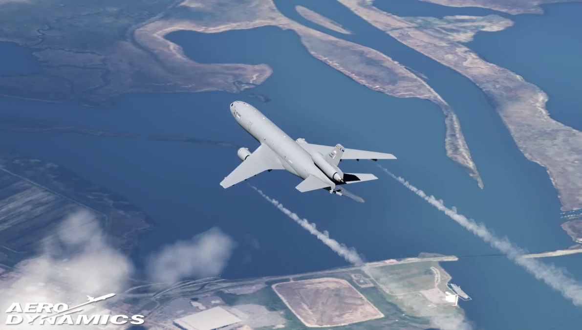
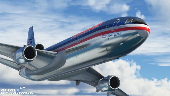
In the latest development update from Aero Dynamics, the team behind the highly anticipated freeware KC-10/DC-10 for Microsoft Flight Simulator, significant advancements have been revealed in the now long-winded development of this iconic aircraft. The update, rich in detail and enthusiasm, highlights the team’s dedication across three critical areas: Exterior Detailing, Cockpit Customization, and Backend Operations. It begins to show a product that is seemingly getting closer to its release… nearly 3 years since we first began to hear about it!
Exterior Detailing
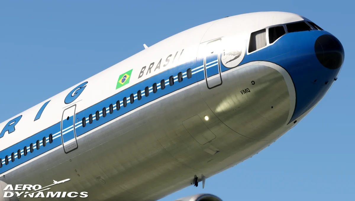
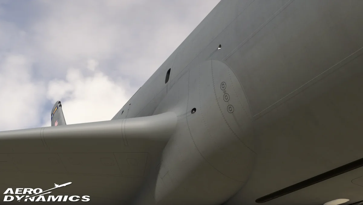
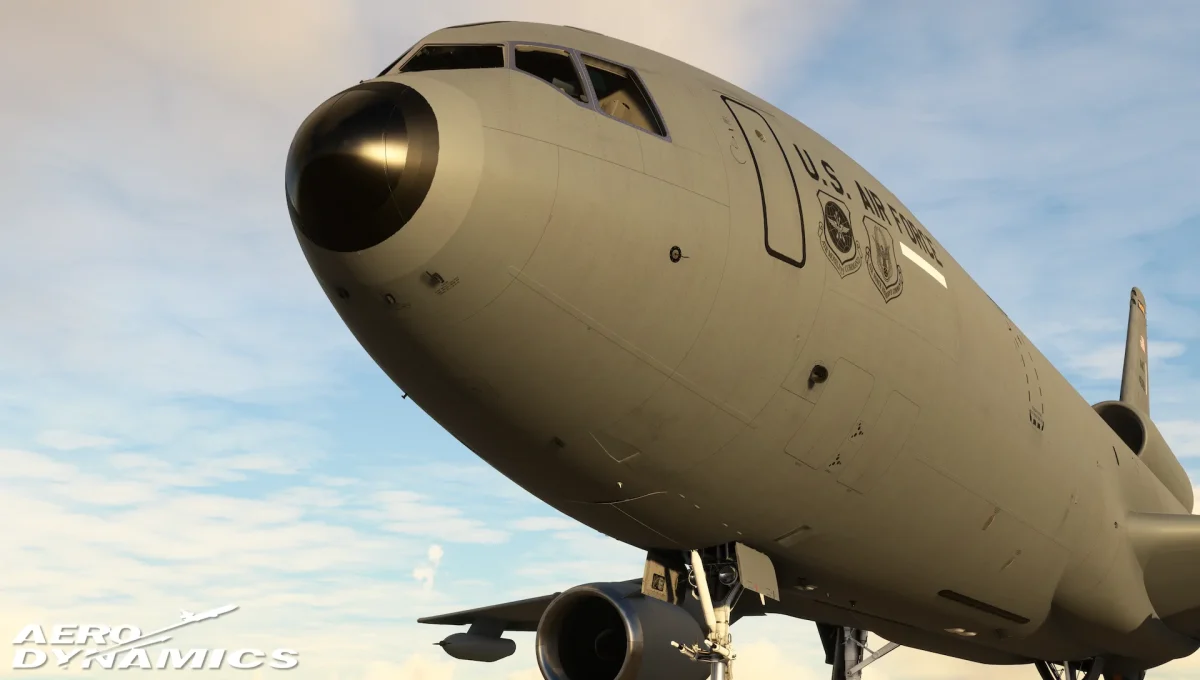
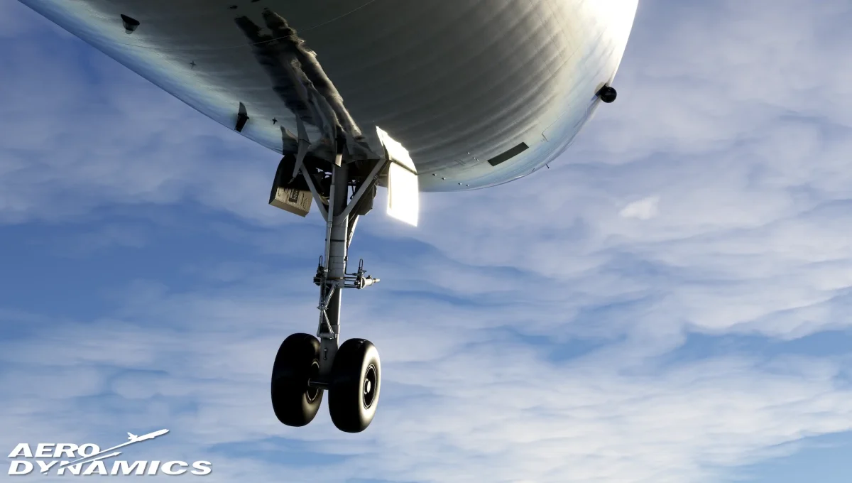
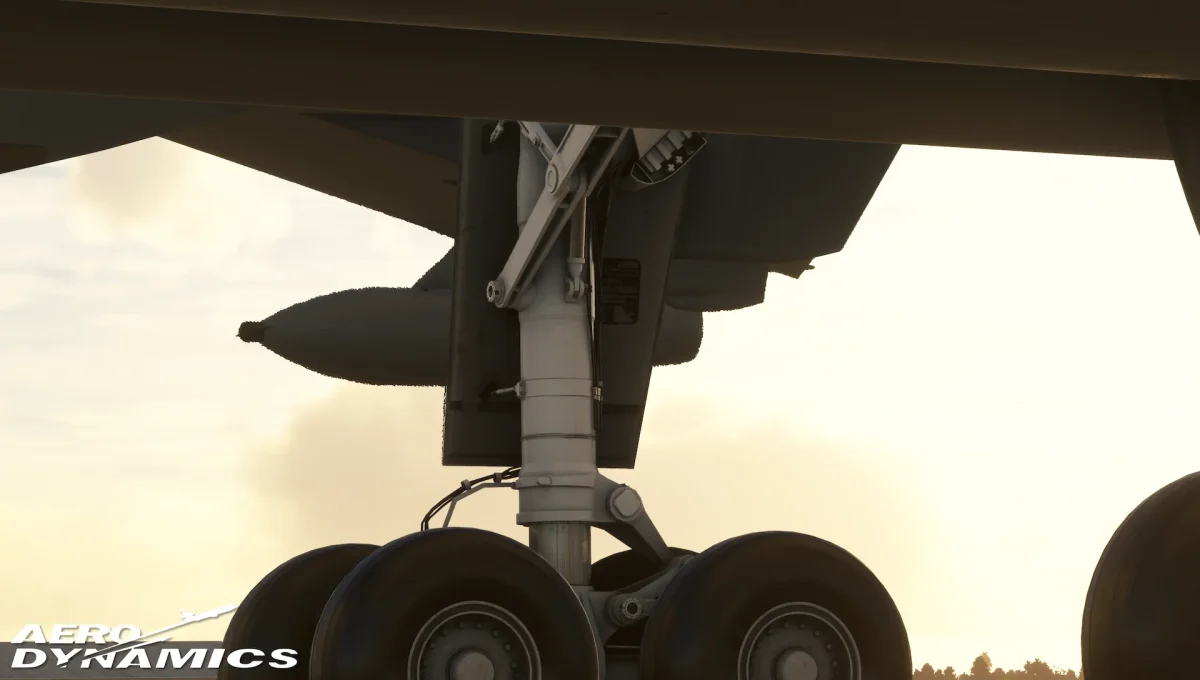
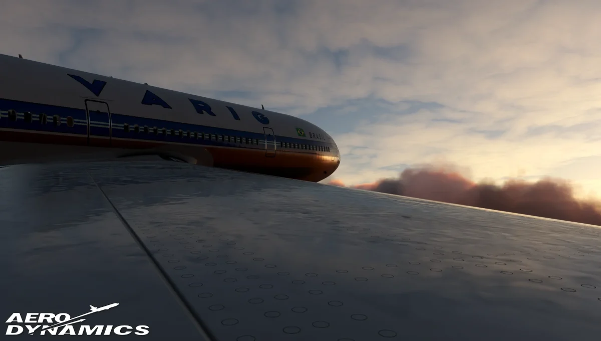
Aero Dynamics has taken the aircraft’s exterior detailing to new heights, focusing on recreating every rivet, panel, and antenna with exceptional fidelity. This quarter’s efforts have introduced realistic rivet patterns and wear patterns, significantly enhancing the aircraft’s visual appeal and immersion.
The team’s dedication to accuracy extends to the replication of panels, doors, and interactive elements, such as the ground electrical power panel and wing refueling panels, ensuring an authentic interaction with the aircraft.
Cockpit Customization
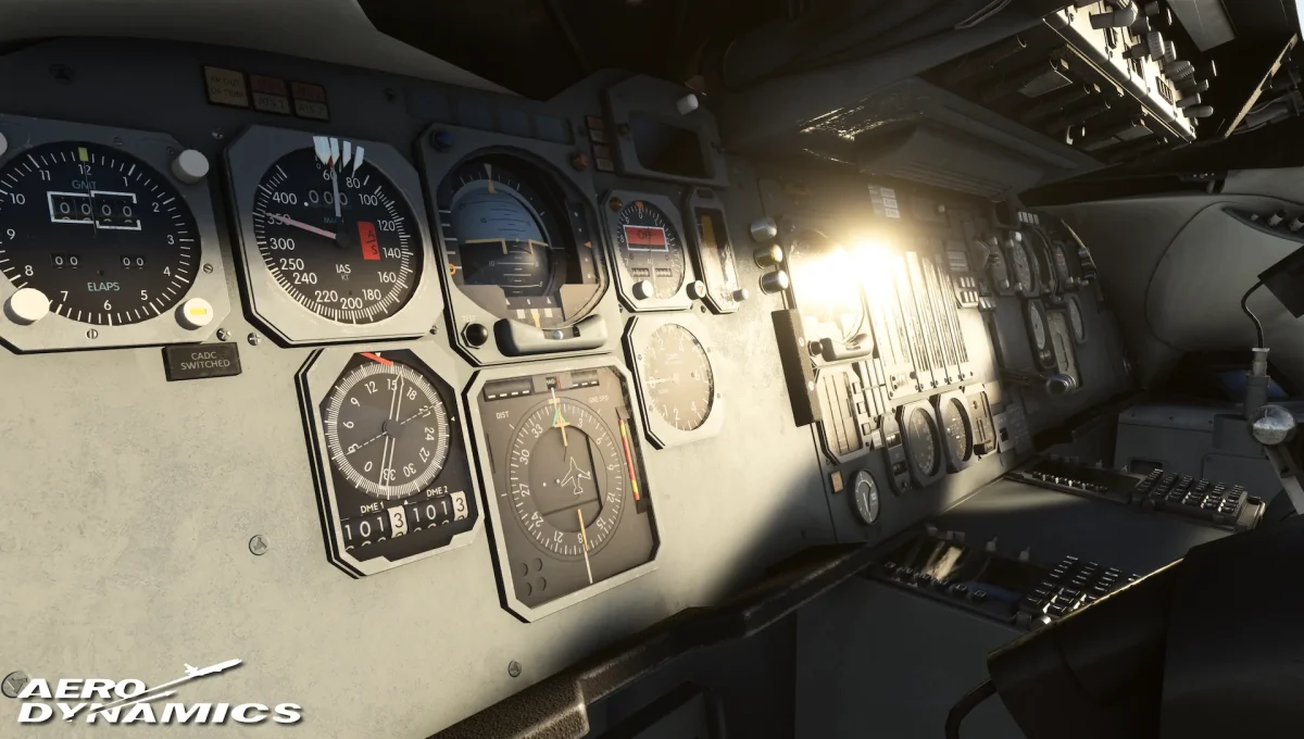
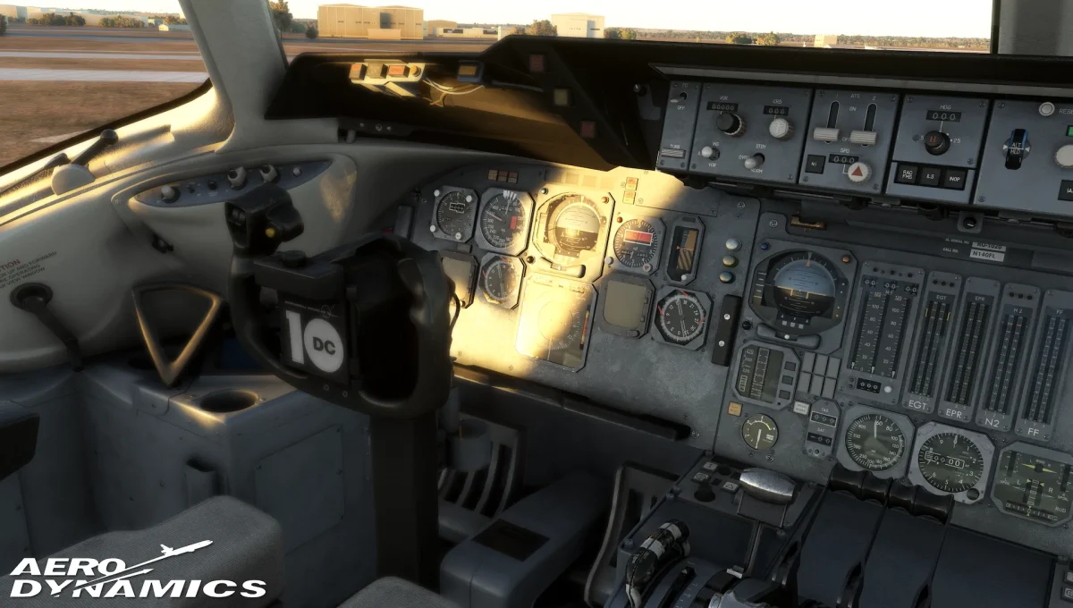
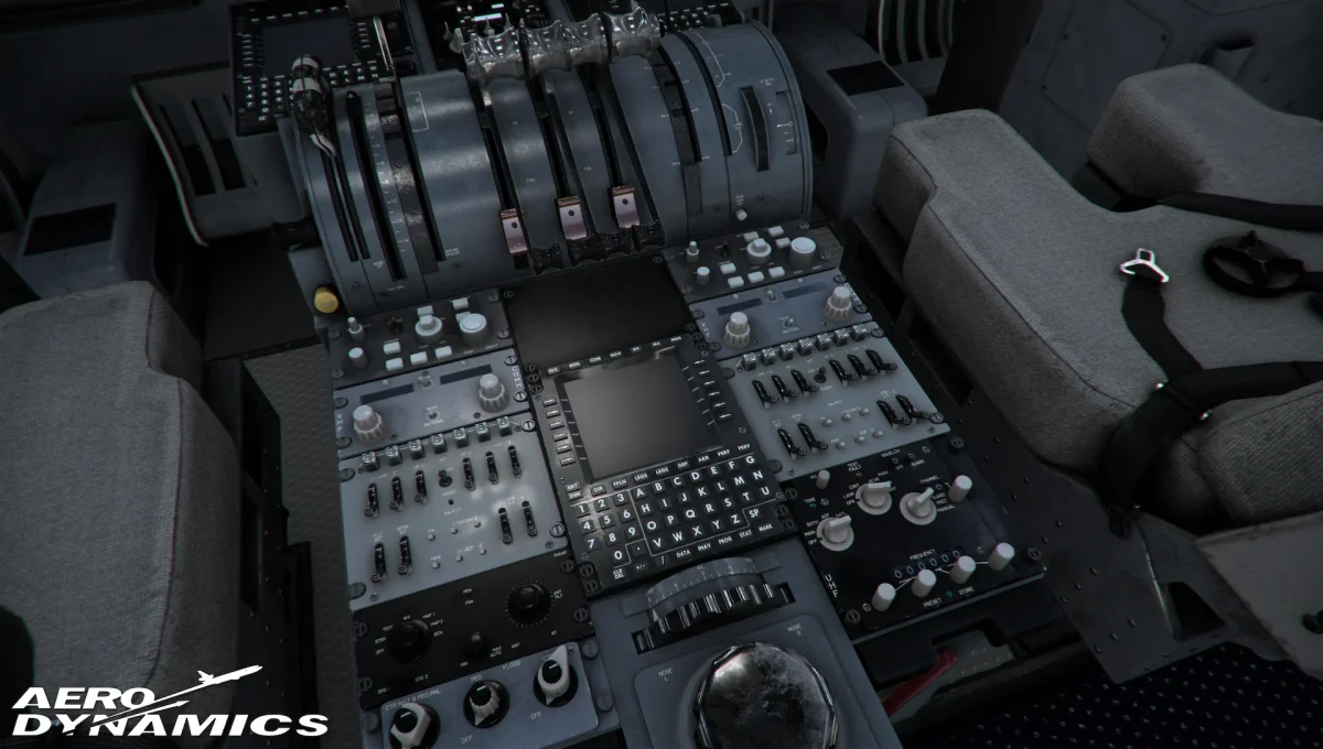
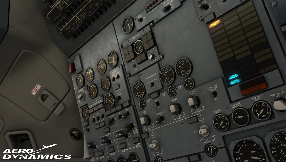
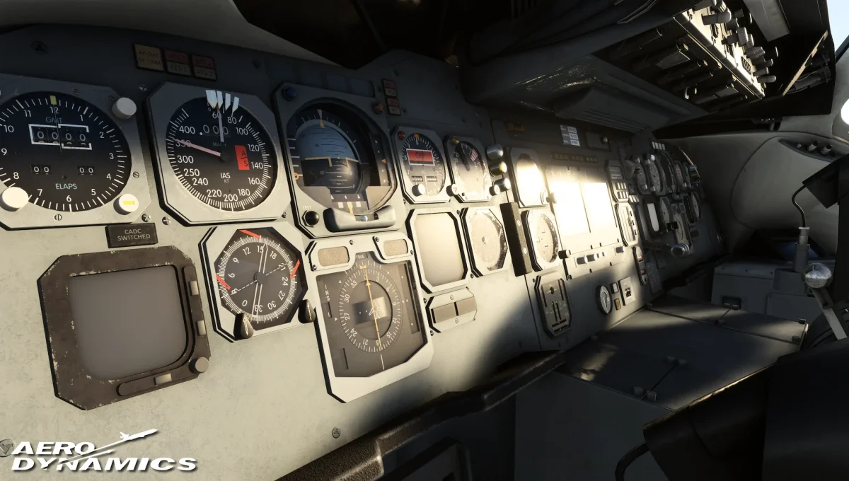
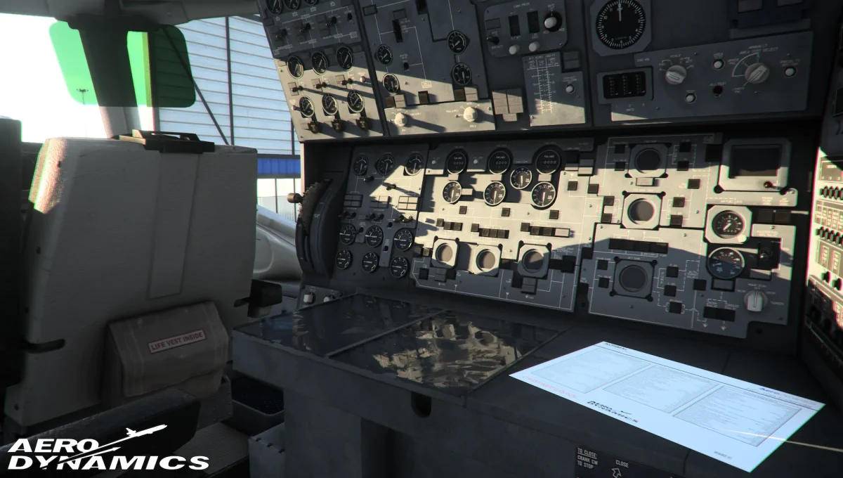
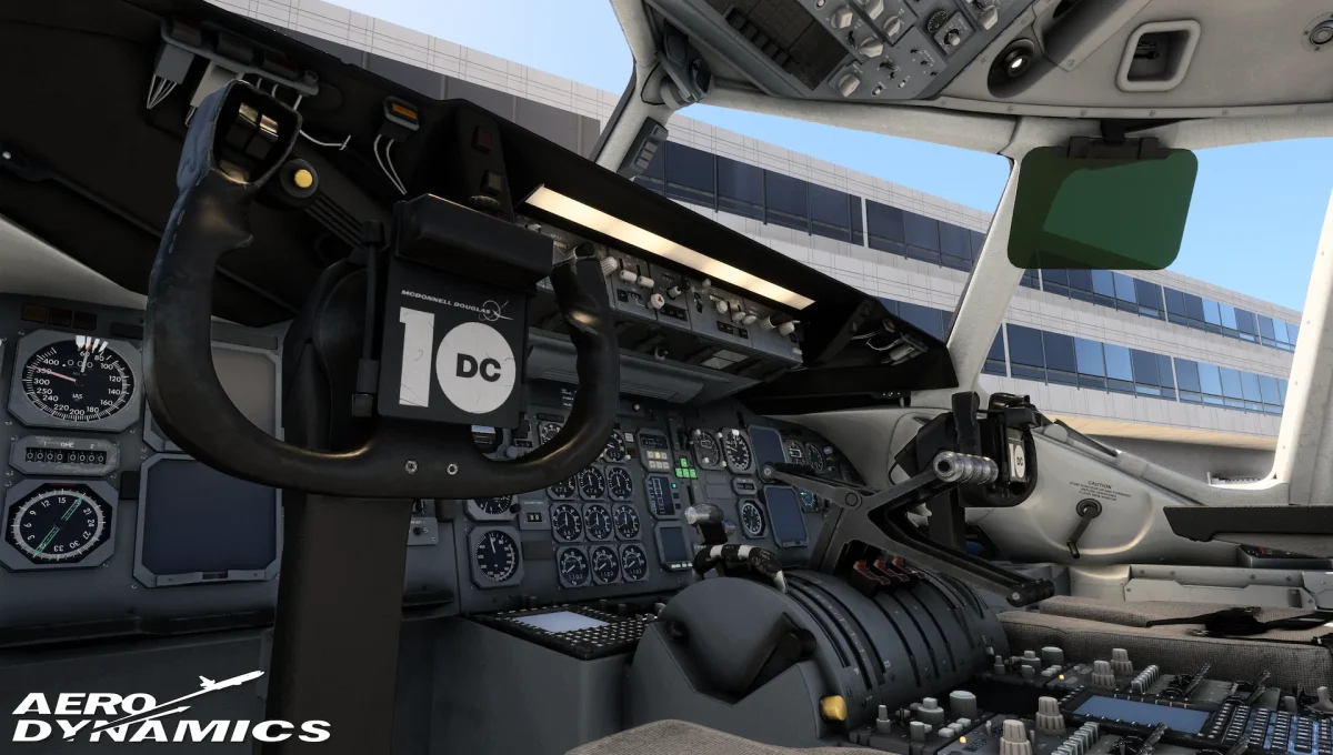
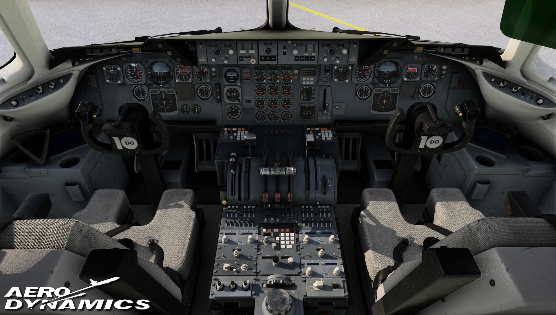
The cockpit of the KC-10/DC-10 has received substantial attention, with Aero Dynamics working on accurately modeling different cockpit configurations for the various aircraft variants. Simmers will have the option to customize their cockpit environment, choosing from a variety of gauges and systems to match their personal, operational, or historical preferences.
This level of customization, including the ability to modify the flight engineer’s station, promises to deliver a cockpit experience that is both unique and deeply immersive. The new preview images of the flight deck are easily the most impressive ones we’ve seen so far and look about as good as other highly-rated airliners already available!
Backend Operations
Behind the impressive visuals, the team has been hard at work on the backend operations that ensure the aircraft operates realistically. This involves the meticulous development of backend systems that govern the aircraft’s various functionalities, aligning with technical specifications from authoritative sources.
A highlight of this development is the detailed modeling of the APU’s interaction with the pneumatic and electrical systems, which showcases the team’s commitment to realism and authenticity.
In-Depth Systems Interplay
In the update, Aero Dynamics has provided an in-depth look at the systems interplay, particularly focusing on the APU startup procedure. They point to a technical description of this procedure and promise that the whole process has been faithfully represented in their virtual rendition of the DC-10:
- When the APU MASTER switch is moved to RUN, this sends power to the APU Inlet door relay which controls the opening of the APU Inlet door. The door takes 20-25 seconds to open, and upon completion will close the contacts in another relay which then connects the power to the Electronic Control Board (ECB) which regulates various APU Operations. When there is a momentary movement of the APU Master switch to the START position, this signals to the ECB to perform the startup procedure. There are multiple stages to the APU start, and multiple self checks by the ECB to ensure safe starting conditions. If any of these conditions are not met, then the APU will perform an auto-shutdown. For instance, before commencing the startup procedure by powering the START RELAY DRIVER, the ECB will check whether the APU’s current N2 is less than 50% and no existing shutdown signal is present. Once the START RELAY is powered, a starter motor will drive the engine shaft to start pulling in air from outside. At the same time, power is supplied to the Start Period Timer. If 60 seconds should pass prior to the starter motor disengaging, the auto shutdown sequence will start, as this indicates suboptimal starting conditions, due to a high likelihood of unbalanced air to fuel ratio at that stage. While the N2 picks up RPM, this generates electrical pulses which are converted to DC current and is used to electrically measure N2 rpm percentage.
- Once N2 reaches 6.5% N2, the ECB evaluates whether it is safe to start ignition. This includes checking the current ambient temperature isn’t above 815 degrees Celsius, which is detected by EGT thermocouples, no emergency shutdown signal, and N2 > 6.5% and < 95%. Given these conditions are satisfied, ignition begins and accelerates the N1 and N2 turbines. There is a coupling of N1 and N2, which can be modeled a variety of ways, and we’ve chosen to model it with a good middleground between performance and complexity. This model accounts for some of the current atmospheric conditions, as air density has a huge effect on the N1 and N2, and have been tuned to approximate starts that faithfully represent the real jet, based on various references. This means that every start will be slightly different, and sometimes could result in some interesting cases. For example, on a hot day, the air is less dense which can cause a slow start, which could trigger a shutdown sequence. This is because it is likely that N1 does not reach 10% as N2 crosses 50%, which triggers an auto-shutdown by the ECB. Another possibility is that the max allowable EGT could be exceeded. This max EGT is dynamic based on the N2 speed.
- As N2 gets to 50%, and given that N1 is greater than 10%, more fuel is introduced and this will disconnect the starter motor, which will cause a spike in EGT, and effectively change the acceleration function of N1 and N2 due to more energy being introduced by the fuel. This will trigger a rapid growth of N2 towards 100% and N1 towards 63% (unless you’re above 7000 ft, in which case it’s 89%). As the N1 and N2 values converge to their baseline values, the EGT will also converge to some stable temperature.
- The APU N1 RPM adjusts based on aircraft needs based on the electrical and pneumatic system. At 63% N1, the APU can power the aircraft electrically, but is unable to do so pneumatically. Once the APU ISOL Valve (powered by electricity) is selected to the open position in the FE Panel, the APU N1 increases to 85% to supply the demanded air. ISOL Valves for the #1-2 and #2-3 engines are automatically opened or closed as N1 crosses 74% RPM given that the switches are in the NORM position. For an engine start, this N1 will rise to 98-100% to supply the demanded air to perform an engine start.
According to Aero Dynamics, this is a small insight into how they’re modeling the aircraft systems, and there will be much more to come!
Looking Ahead
With each update, Aero Dynamics continues to amplify the excitement around their KC-10/DC-10 project, yet they are also nearing a critical juncture: the aircraft’s much-anticipated debut or the risk of it being categorized as vaporware. The wait has been lengthy, and although there has been consistent progress, the prolonged development is increasingly testing the community’s patience.
Nonetheless, the allure of the AE DC-10 remains strong, positioning it as a potentially significant addition for Microsoft Flight Simulator. We remain attentive to its development and, as always, will bring you the latest updates on this exciting project!


